Description:
ESP32 is a powerful module with Wi-Fi, Bluetooth, BLE, and MCU with onboard RF connectivity.
It works on high-frequency operation, higher frequency means higher power consumption.
This means for the battery-backed application we need to optimize the power usage.
If we carefully manage the power modes, we can extend the battery life of ESP32-powered projects.
Simply, we have to keep the ESP32 in sleep mode as long as possible and wake it up, only when we need it.
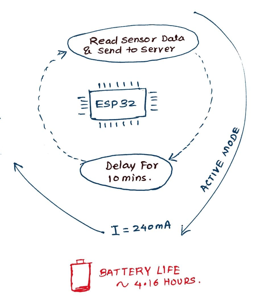
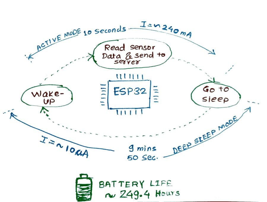
i.e., suppose you are developing a battery (1000mAh) backed application of temperature, and humidity monitoring and sending data to the server every 10 mins, then
Without Sleep Mode 1000 mAh Battery:
With Sleep Mode 1000 mAh Battery:
Power Modes in ESP32
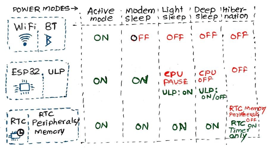
Power Consumption in Various Modes
| Powe Mode | Description | Power Consumption |
| Active (RF Working) | Wi-Fi and Bluetooth ON | 95-240 mA |
| Modem Sleep | CPU ON | Max Speed: 20mA |
| Normal: 5-10mA | ||
| Slow: 3mA | ||
| Light Sleep | - | 0.8 mA |
| Deep Sleep | ULP ON | 150 uA |
| RTC Timer+ RTC Memory | 10 uA | |
| Hibernation | RTC timer Only | 5 uA |
| Power Off | - | 0.1 uA |
Why use Deep Sleep Mode?
To improve the Battery performance and power efficiency of our application.
We have to get creative and use deep sleep mode for the minimum power supply consumption.
For example:

Deep Sleep mode:
In deep sleep mode CPU is powered down. However, the ULP (Ultra Low Power) co-processor does sensor measurements and wakes up the main system, based on the monitored data from the sensor. This is known as ULP Sensor-monitored pattern.
Note: in Deep Sleep mode, CPU+ Memory is powered down. While waking up ESP32 will restart with a reset. This means program execution starts from the beginning on every wake-up.
Deep Sleep Wake Stubs: ESP32 supports running a “deep sleep wake stub” when coming out of deep sleep. This function runs immediately as soon as the chip wakes up - before any normal initialization or bootloader. We will see more about this in a later part.
esp_deep_sleep_start() This function is used to in deep sleep mode.
But before putting ESP32 in Deep Sleep mode, we have to configure the Wake-Up source.
Saving Data in RTC Memory
In Deep Sleep mode, along with the main CPU, the memory of the chip is also powered down, and everything is erased from memory. However, RTC memory is kept powered ON. So data can be stored and retrieved after waking up from RTC memory.
So, if we have to use the data over sleep/ reboot, we need to store it in the RTC memory by defining a global variable with the RTC_DATA_ATTR attribute. It’s straightforward.
For example,
RTC_DATA_ATTR int bootCount= 0;
Wake Up Source
There are four Wake Up sources available, we can use them individually or combine them as well
- Timer
- Touch Pins
- External Interrupts (ext0 and ext1)
- ULP co-processor
*ULP Co-Processor: we will see this in a later part
ESP32 Deep Sleep Mode: Timer Wake UP
RTC controller has a built-in timer that can be used to wake up the ESP32 after a defined amount of time.
Time is specified in microseconds. It’s very simple and straight with Arduino IDE.
Function:
esp_sleep_enable_timer_wakeup(time_in_us)
Program:
Putting the ESP32 in Deep Sleep mode and waking it up using Timer source after 5 seconds. Also, we have stored the bootCount variable in RTC Memory and printed boot count.
/*
  ESP32 Deep Sleep Mode Timer Wake UP
 http:://www.electronicwings.com
*/


#define Time_To_Sleep 5   //Time ESP32 will go to sleep (in seconds)
#define S_To_uS_Factor 1000000ULL      //Conversion factor for micro seconds to seconds

RTC_DATA_ATTR int bootCount= 0;

void setup() {
  Serial.begin(115200);
  delay(1000); //Take some time to open up the Serial Monitor

  //Increment boot number and print it every reboot
  ++bootCount;
  Serial.println("Boot number: " + String(bootCount));

  //Set timer to 5 seconds
 esp_sleep_enable_timer_wakeup(Time_To_Sleep * S_To_uS_Factor);
  Serial.println("Setup ESP32 to sleep for every " + String(Time_To_Sleep) +
  " Seconds");

  //Go to sleep now
  esp_deep_sleep_start();

  Serial.println("This will not print!!"); // This will not get print,as ESP32 goes in Sleep mode.
}

void loop() {} // We don't need loop as ESP32 will initilize each time.
Output window
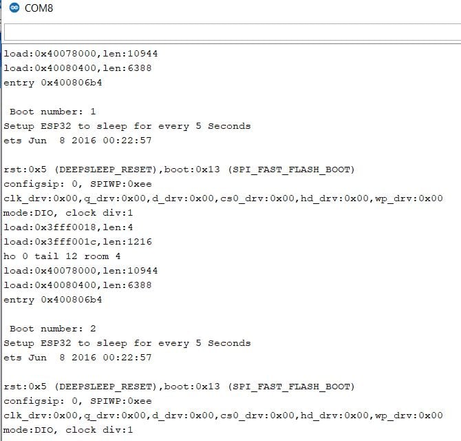
Let’s understand the code:
- First, we define the sleep time i.e., 5 Seconds.
- As we have to provide it to
esp_sleep_enable_timer_wakeup()Function in Microseconds, we have defined a factor for the same. - As we have to measure the boot Count, we have to save the variable in RTC memory, which we have to do by
RTC_DATA_ATTRin the variable definition. - In
Void setup(), we initialize the serial monitor and printed the boot count. - Then, we configure the Wake up with timer source for 5 seconds by using
esp_sleep_enable_timer_wakeup() - Finally, we put it in deep sleep mode using
esp_deep_sleep_start(); - ESP32 will go immediately in Deep Sleep mode. CPU will get powered down. So the final function
Serial.println()will not get printed on the serial monitor.
ESP32 Deep Sleep: Touch Pad Wake Up
RTC IO module contains logic to trigger wake up when a touch sensor interrupt occurs.
We need to configure the touch pad interrupt before the ESP32 goes in deep sleep.
Function: function is used to enable touch pad wake-up source.
esp_sleep_enable_touchpad_wakeup()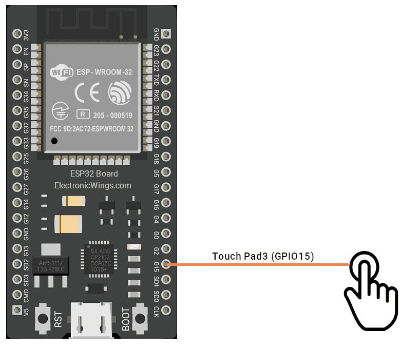
Code
We can find the example code directly in Arduino IDE.
Go to File>> Example>> ESP32>> Deep Sleep, and open TouchWakeUP Sketch.
/*
Deep Sleep with Touch Wake Up
=====================================
This code displays how to use deep sleep with
a touch as a wake up source and how to store data in
RTC memory to use it over reboots

This code is under Public Domain License.

Author:
Pranav Cherukupalli <[email protected]>
*/

#define Threshold 40 /* Greater the value, more the sensitivity */

RTC_DATA_ATTR int bootCount = 0;
touch_pad_t touchPin;
/*
Method to print the reason by which ESP32
has been awaken from sleep
*/
void print_wakeup_reason(){
  esp_sleep_wakeup_cause_t wakeup_reason;

  wakeup_reason = esp_sleep_get_wakeup_cause();

  switch(wakeup_reason)
  {
    case ESP_SLEEP_WAKEUP_EXT0 : Serial.println("Wakeup caused by external signal using RTC_IO"); break;
    case ESP_SLEEP_WAKEUP_EXT1 : Serial.println("Wakeup caused by external signal using RTC_CNTL"); break;
    case ESP_SLEEP_WAKEUP_TIMER : Serial.println("Wakeup caused by timer"); break;
    case ESP_SLEEP_WAKEUP_TOUCHPAD : Serial.println("Wakeup caused by touchpad"); break;
    case ESP_SLEEP_WAKEUP_ULP : Serial.println("Wakeup caused by ULP program"); break;
    default : Serial.printf("Wakeup was not caused by deep sleep: %d\n",wakeup_reason); break;
  }
}

/*
Method to print the touchpad by which ESP32
has been awaken from sleep
*/
void print_wakeup_touchpad(){
  touchPin = esp_sleep_get_touchpad_wakeup_status();

  switch(touchPin)
  {
    case 0  : Serial.println("Touch detected on GPIO 4"); break;
    case 1  : Serial.println("Touch detected on GPIO 0"); break;
    case 2  : Serial.println("Touch detected on GPIO 2"); break;
    case 3  : Serial.println("Touch detected on GPIO 15"); break;
    case 4  : Serial.println("Touch detected on GPIO 13"); break;
    case 5  : Serial.println("Touch detected on GPIO 12"); break;
    case 6  : Serial.println("Touch detected on GPIO 14"); break;
    case 7  : Serial.println("Touch detected on GPIO 27"); break;
    case 8  : Serial.println("Touch detected on GPIO 33"); break;
    case 9  : Serial.println("Touch detected on GPIO 32"); break;
    default : Serial.println("Wakeup not by touchpad"); break;
  }
}

void callback(){
  //placeholder callback function
}

void setup(){
  Serial.begin(115200);
  delay(1000); //Take some time to open up the Serial Monitor

  //Increment boot number and print it every reboot
  ++bootCount;
  Serial.println("Boot number: " + String(bootCount));

  //Print the wakeup reason for ESP32 and touchpad too
  print_wakeup_reason();
  print_wakeup_touchpad();

  //Setup interrupt on Touch Pad 3 (GPIO15)
  touchAttachInterrupt(T3, callback, Threshold);

  //Configure Touchpad as wakeup source
 esp_sleep_enable_touchpad_wakeup();

  //Go to sleep now
  Serial.println("Going to sleep now");
  esp_deep_sleep_start();
  Serial.println("This will never be printed");
}

void loop(){
  //This will never be reached
}
In this code, you can find the additional functions such as
void print_wakeup_reason()  //to print the reason by which ESP32 wakes up
void print_wakeup_touchpad() //to print the touchpad which awaken the ESP32
Setting Threshold
We have to set the touchpad threshold as per our application, here it is set to 40.
Connect the jumper wire on GPIO15 for test and touch the open lead. Test it for various threshold that is appropriate for the application.
{Image with ESP32 and Jumper Wire connected to it}
Attach Interrupts on TouchPad
We have to attach interrupts to touch-sensitive GPIO Pins.
When touch is detected on a specific GPIO, a callback function will get executed.
//Setup interrupt on Touch Pad 3 (GPIO15)
touchAttachInterrupt(T3, callback, Threshold);
For waking ESP32 via other pins, just attach the interrupts to those pins.
However, the Callback function will get only be executed when ESP32 is awake.
If you are putting some code to execute in the callback function, then we must consider the following points.
- It is an interrupt function. For good practice, it should be compact. i.e. setting a flag.
- The callback function will execute only when ESP32 is awake. If ESP32 is asleep and we wake it up by touchpad with press and release instantly, the function will not execute.
- To execute the function we have to touch and hold the pin for a while, as per delay in the program.
- Some Delay in the program flow (Before going into Deep Sleep) will be a good idea for the proper execution of the callback function.
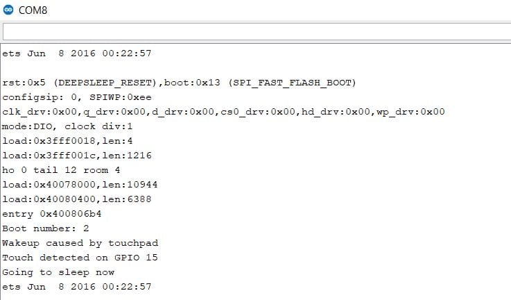
Output
ESP32 External Interrupt Wake Up
It’s simple, We can awake ESP32 simply by providing low or high levels on ESP32 pins.
RTC Controllers contain logic to trigger wakeup using RTC GPIOs.
ext0 – Use it when we have to wake up the ESP32 by one particular pin. We can use any RTC GPIOs.
ext1 – Use it when you have several buttons for the wake-up.
ESP32 wake up using ext0
To use ext0, we need to use the following function.
esp_sleep_enable_ext0_wakeup(GPIO_NUM_X, level)Arguments
GPIO_NUM_Xwhere ‘X’ represents the GPIO number of RTC GPIO.- the level represents the 0 or 1 which will trigger the wake up.
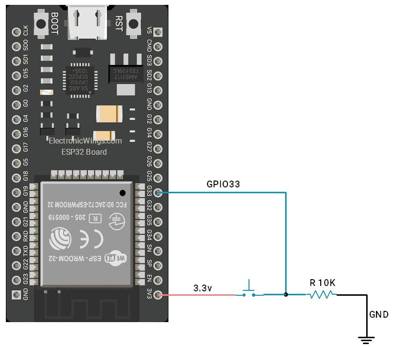
To test, we will use GPIO33 and trigger wake up on HIGH.
esp_sleep_enable_ext0_wakeup(GPIO_NUM_33,1); //1 = High, 0 = LowSchematic
Code
You can find example code in Arduino IDE with the ESP32 library. Go to File > Examples > ESP32 > Deep Sleep > ExternalWakeUp:
/*
Deep Sleep with External Wake Up
=====================================
This code displays how to use deep sleep with
an external trigger as a wake up source and how
to store data in RTC memory to use it over reboots

This code is under Public Domain License.

Hardware Connections
======================
Push Button to GPIO 33 pulled down with a 10K Ohm
resistor

NOTE:
======
Only RTC IO can be used as a source for external wake
source. They are pins: 0,2,4,12-15,25-27,32-39.

Author:
Pranav Cherukupalli <[email protected]>
*/

#define BUTTON_PIN_BITMASK 0x200000000 // 2^33 in hex

RTC_DATA_ATTR int bootCount = 0;

/*
Method to print the reason by which ESP32
has been awaken from sleep
*/
void print_wakeup_reason(){
  esp_sleep_wakeup_cause_t wakeup_reason;

  wakeup_reason = esp_sleep_get_wakeup_cause();

  switch(wakeup_reason)
  {
    case ESP_SLEEP_WAKEUP_EXT0 : Serial.println("Wakeup caused by external signal using RTC_IO"); break;
    case ESP_SLEEP_WAKEUP_EXT1 : Serial.println("Wakeup caused by external signal using RTC_CNTL"); break;
    case ESP_SLEEP_WAKEUP_TIMER : Serial.println("Wakeup caused by timer"); break;
    case ESP_SLEEP_WAKEUP_TOUCHPAD : Serial.println("Wakeup caused by touchpad"); break;
    case ESP_SLEEP_WAKEUP_ULP : Serial.println("Wakeup caused by ULP program"); break;
    default : Serial.printf("Wakeup was not caused by deep sleep: %d\n",wakeup_reason); break;
  }
}

void setup(){
  Serial.begin(115200);
  delay(1000); //Take some time to open up the Serial Monitor

  //Increment boot number and print it every reboot
  ++bootCount;
  Serial.println("Boot number: " + String(bootCount));

  //Print the wakeup reason for ESP32
  print_wakeup_reason();

  /*
  First we configure the wake up source
  We set our ESP32 to wake up for an external trigger.
  There are two types for ESP32, ext0 and ext1 .
  ext0 uses RTC_IO to wakeup thus requires RTC peripherals
  to be on while ext1 uses RTC Controller so doesnt need
  peripherals to be powered on.
  Note that using internal pullups/pulldowns also requires
  RTC peripherals to be turned on.
  */
 esp_sleep_enable_ext0_wakeup(GPIO_NUM_33,1); //1 = High, 0 = Low

  //If you were to use ext1, you would use it like
  //esp_sleep_enable_ext1_wakeup(BUTTON_PIN_BITMASK,ESP_EXT1_WAKEUP_ANY_HIGH);

  //Go to sleep now
  Serial.println("Going to sleep now");
  esp_deep_sleep_start();
  Serial.println("This will never be printed");
}

void loop(){
  //This is not going to be called
}
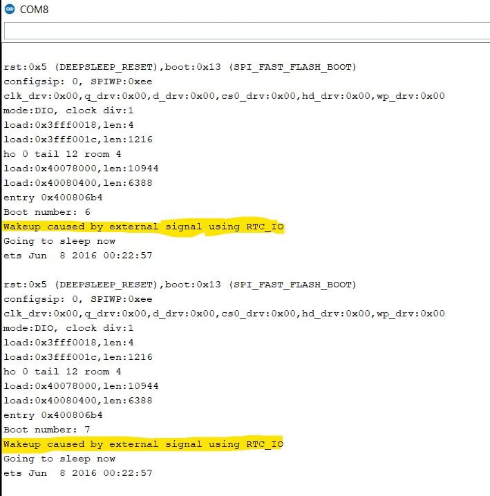
Output
ESP32 wake up using Ext1
Ext1 allows us to wake up the ESP32 using multiple buttons. We don’t have to depend on just one pin like ext0.
Code is similar, instead of using esp_sleep_enable_ext0_wakeup() function, we have to use esp_sleep_enable_ext1_wakeup().
Function:
esp_sleep_enable_ext1_wakeup(BUTTON_PIN_BITMASK,ESP_EXT1_WAKEUP_ANY_HIGH);First Argument: BUTTON_PIN_BITMASK: It’s straight, RTC GPIOs which we are going to use, we have to set it's bit no as ‘1’.
For example, we are using GPIO2 and GPIO33
[Adding Sketch Image].
So the value will be: 0x200000004.
Second Argument is
- ESP_EXT1_WAKEUP_ANY_HIGH means Wake up ESP32 if any pin gets High.
- ESP_EXT1_WAKEUP_ALL_LOW: Wake up if all selected pins are low
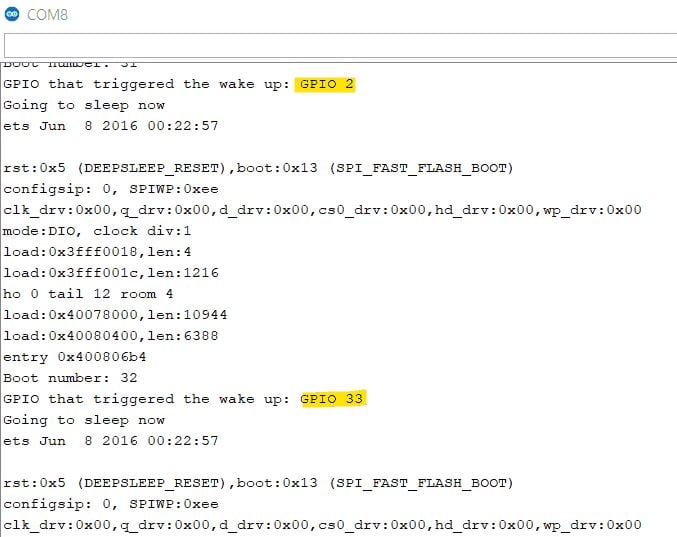
Identifying the GPIO which triggered the ESP32 wake-up
When we use multiple GPIOs, and we want to know the pin which triggers the Wake Up:
esp_sleep_get_ext1_wakeup_status()This function returns a number with the GPIO number as an exponent: 2^(GPIO). So we can use the following calculations for getting the GPIO number.
GPIO = log(RETURNED_VALUE)/log(2)
Schematic
GPIO2 and GPIO33 are used for the ext1 interrupt.

Code
/*
  ESP32 Deep Sleep Mode ext1 interrupt wake up
 http:://www.electronicwings.com
*/


#define BUTTON_PIN_BITMASK 0x200000004 // GPIOs 2 and 33

RTC_DATA_ATTR int bootCount = 0;

/*
Method to print the GPIO that triggered the wakeup
*/
void print_GPIO_wake_up(){
  uint64_t GPIO_reason = esp_sleep_get_ext1_wakeup_status();
  Serial.print("GPIO that triggered the wake up: GPIO ");
  Serial.println((log(GPIO_reason))/log(2), 0);
}

void setup(){
  Serial.begin(115200);
  delay(1000); //Take some time to open up the Serial Monitor

  //Increment boot number and print it every reboot
  ++bootCount;
  Serial.println("Boot number: " + String(bootCount));

  //Print the GPIO used to wake up
  print_GPIO_wake_up();

 esp_sleep_enable_ext1_wakeup(BUTTON_PIN_BITMASK,ESP_EXT1_WAKEUP_ANY_HIGH);

  //Go to sleep now
  Serial.println("Going to sleep now");
  delay(1000);
  esp_deep_sleep_start();
  Serial.println("This will never be printed");
}

void loop(){
  //This is not going to be called
}
Output
Summary
Important functions to remember!
To Enable timer as wake Up Source:
esp_sleep_enable_timer_wakeup(time_in_us)Putting ESP32 in Deep Sleep Mode:
esp_deep_sleep_start()Using Touch Pad as wake up source: attaching interrupt to the pin
touchAttachInterrupt(Touchpin, callback, Threshold)Enabling the touch pin as a wake-up source
esp_sleep_enable_touchpad_wakeup()Enabling ext0 as wakeup source
esp_deep_sleep_enable_ext0_wakeup(GPIO_NUM_x,level)Enabling ext1 as a wakeup source, we can use multiple pins with bit masks
esp_sleep_enable_ext1_wakeup(BUTTON_PIN_BITMASK,ESP_EXT1_WAKEUP_ANY_HIGH)
Components Used |
||
|---|---|---|
| ESP32 WROOM WiFi Development Tools - 802.11 ESP32 General Development Kit, embeds ESP32-WROOM-32E, 4MB flash. |
X 1 | |
