PIC Microcontrollers
- PIC microcontrollers are manufactured by Microchip. They are available in 8-bit, 16-bit, and 32-bit.
- 8-bit PIC microcontrollers have various families which are as follows-
| Features | Baseline | Mid-Range | Enhanced Mid-Range | Advanced PIC18 |
| Families | PIC10, PIC12, PIC16 | PIC10, PIC12 | PIC12Fxxx,PIC16Fxxx | PIC 18 |
| Program Memory | Max 3 KB | Max 14 KB | Max 28 KB | Max 128 KB |
| Data Memory | Max 138 Bytes | Max 368 Bytes | Max 1-5 KB | Max 4 KB |
| Performance | 5 MIPS | 5 MIPS | 8 MIPS | 16 MIPS |
| Features |
| Addition to baseline
| Addition to midrange
|
|
- Most of the families are pin-compatible but assigned functions are different for different families.
- For example, PIC16F877A has I2C (SDA and SCL) pins multiplexed with PORTC whereas in PIC18F4550 they are multiplexed with PORTB but both families are pin compatible.
- In family names, there are suffixes used in between which tell -
PIC18FXXX – ‘F’ implies Flash Program Memory
PIC16CXXX – ‘C’ implies EPROM Program Memory
PIC18LFXXX – ‘LF” implies Low Voltage operation
- It varies from family to family.
- Whenever a new part is designed to replace an older part, a new version of the part is obtained by adding extra alphabet at the end like 16F877 and 16F877A.
The following section will cover the PIC18 detailed introduction as it is more preferred for development.
Let’s start with the PIC18F4550 device in the PIC18 family.
PIC18F4550 is an 8-bit RISC architecture microcontroller. Its specifications are
- Timer: One 8-bit and three 16-bit Timers i.e. Timer0-Timer3.
- USART: 1 In-built Enhanced USART.
- ADC: 10-bit 13 channel ADC.
- Capture, Compare, and PWM module (CCP) and Enhanced CCP module.
- USB: USB V2.0 support transfer speed 1.5Mb/s to 12Mb/s.
- Master Synchronous Serial Port (MSSP) having I2C and SPI protocol.
- 256 Bytes of EEPROM, 32Kbytes of Flash memory, and 2KB internal SRAM.
- PORTS: A, B, C, D, and E.
- Streaming Parallel Port for USB streaming transfers.
- Three External Interrupts.
- Oscillator:
- Four Crystal modes, including High Precision PLL for USB
- Two External Clock modes, up to 48 MHz
- Internal Oscillator having 8-user selectable frequency from 32 kHz-8 MHz
- Secondary Oscillator using Timer1 @ 32 kHz
- LIN bus support.
PIC18F4550 Pin Diagram
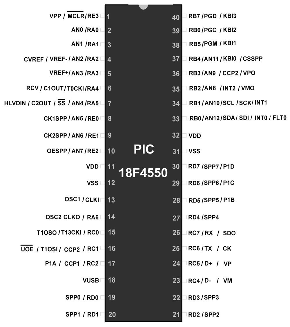
It has 5 Ports, and each Port has the following 3 Registers:
- TRIS – Used as a data direction register (0-output and 1-input).
- LAT – Data Output Register.
- PORT – Used to read levels on input pins.
- PORTB and PORTD have weak internal Pull-ups.
- Also on Power-On Reset (POR), Port Pins which are multiplexed with ADC pins act as ADC pins (default).
- To access these GPIO pins first change the default ADC mode to Digital pins using PBADEN register.
Features of PIC18F4550 MCU
Timer
- It has a built-in Timer module which can be used for many applications like generating precise delay, Pulse counting, Pulse measurement.
- Timer0, Timer2, and Timer3 are 16-bit Timer whereas Timer1 is an 8-bit timer.
- To use these Timer modules they have their individual Control and Status Registers.
- To use Timer as a counter or for event counting, we need to connect the external pulse to RA4 for Timer0 and to RC0 for Timer1. These signals are nothing but T1CKI and T3CKI respectively.
ADC
- It has a 10-bit 13 channel ADC. The channels are named as AN0, AN1, AN2….AN12.
- It is used to read analog signals from sensors like Temperature, Humidity, accelerometer, and convert them to digital for processing.
UART
- It also has Universal Asynchronous Receiver Transmitter (UART) which is used to communicate between two devices serially. For long-distance communications, usually, the serial protocol is preferred.
- Most of the electronic modules like GSM, GPS, Bluetooth, Wi-Fi use UART communication with different Baud Rates such as 9600,115200, etc.
- To implement this communication, Pins Rx for receiver and Tx for Transmitter is used.
External Interrupt
- INT0, INT1, and INT2 pins are used for External Interrupt. The application of this interrupt is to detect the desired event of the incoming pulse and take respective action. These desired events are Positive edge Trigger or Negative Edge Trigger.
Capture/Compare/PWM CCP Module
- It has a Capture/Compare/PWM (CCP) module which is used for different applications.
- Capture- It is used to measure the frequency, pulse, or duty cycle of the input pulse. To do this, connect the input pulse to the RC2 pin and configure capture mode.
- Compare- It is used to generate a square wave. To do this load the count in a register which will compare with Timer and when a match occurs it will generate the desired high or low pulse output at RC2 pin.
- PWM – It is used for different applications like controlling the speed of DC motor, changing the intensity of the LED, generation of Sine wave, etc.
Master Synchronous Serial Port (MSSP)
- The Master Synchronous Serial Port (MSSP) module is a serial interface, useful for communicating with other peripheral or microcontroller devices.
- These peripheral devices may be serial EEPROMs, shift registers, display drivers, A/D converters, etc.
The MSSP module can operate in one of two modes:
1. I2C
- I2C- It is a Two-Wire Communication Protocol. It has only 2-wire i.e. SDA (Serial Data) and SCL (Serial Clock). SDA and SCL are multiplexed with PortB.0 and PORTB.1 pin respectively.
- The speed of this protocol ranges from 100 Khz-400 KHz.
- This protocol is used in many interfacing applications like Gyroscope, Magnetometer.
2. SPI
- SPI – It is also a serial communication protocol that has 4 wire i.e. SDI (Serial Data Input), SDO (Serial Data Output), SCK (Serial Clock), and SS’ (Slave select).
- It is used for communicating between devices like SD cards, ADC chips, etc.
Both SPI and I2C protocols have speed greater than UART communication. Both are Master-Slave Protocol.
Universal Serial Bus (USB)
- It has an inbuilt USB which is also a medium of communication. It is a parallel port communication. It provides a Streaming Parallel Port (SPP) as a high-speed interface for moving data to and from an external system.
Power Saving
- It is necessary for some applications where power constraint is important. To make the device Power efficient, it provides the ability to put device in sleep mode when it is idle. This mode is also called as Power saving mode.
Components Used |
||
|---|---|---|
| PIC18f4550 PIC18f4550 |
X 1 | |
| PIC16f877a PIC16f877a |
X 1 | |
| PICKit 4 MPLAB PICKit 4 MPLAB |
X 1 | |