Introduction
Timers in microcontrollers are used for introducing delay, counting events, generating waveforms, and also for PWM generation.
Delays in a microcontroller can be induced by either of the two ways –
- Provide delay using software (through code using loops). But, a delay provided in this way forces the microcontroller to put all its resources for the processing of the loops, and thus blocks the code execution.
- Providing delay using the timer in the microcontroller. In this approach, the delay is provided by loading a count in a timer. So when a timer interrupt is generated current execution will move to the ISR to serve the task. But when there is no timer interrupt it will perform another task. Therefore, we can say it is a kind of non-blocking function.
Let us discuss timers in the PIC18F4550 microcontroller.
PIC18F4550 has 4 in-built timers
- Timer0 : 16-bit
- Timer1 : 16-bit
- Timer2 : 8-bit
- Timer3 : 16-bit
Out of the four timers in PIC18F4550, we will be discussing here Timer1. The working of the rest of the timers is the same. To generate a time delay using Timer1, we have to calculate a count of the desired time.
How to calculate count for Timer?
Let’s take an example. Suppose we have to generate a delay of 1 ms having 8 MHz oscillator frequency of PIC18F4550. To do this, we need to find the period of the instruction cycle.
Fosc = 8 MHz
PIC18F4550 timer uses frequency as follows:
FTIMER = 8 MHz / 4 = 2 MHz
This 2 MHz frequency is fed to the PIC timer.
Then, to find the period which will be taken by the timer to increment the count,
Period = 1 / 2 MHz = 0.5 us
Therefore, after each 0.5 us time elapses, the timer value will get incremented by 1.
To find the count needed for a delay of 1 ms,
Count = Desired Delay / Timer Period
Count = 1 ms / 0.5 us = 2000
Before we load this count in the timer, we first need to subtract it from 65536. The reason we need to subtract it is that the timer is 16-bit. Therefore,
65536 – count = 65536 – 2000 = 63536
Converting this count into hex we get 0xF830. Load this hex value in the Timer1 i.e. TMR1 register. TMR1 is a 16-bit register that is used to load the count for Timer1.
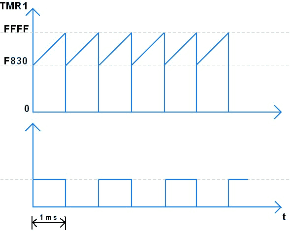
Timer1 Interrupt
The TMR1 register gets incremented from this loaded value to the highest value i.e. 0xFFFF. After an overflow occurs in the register, it resets to 0 and the TMR1IF overflow interrupt flag gets set.
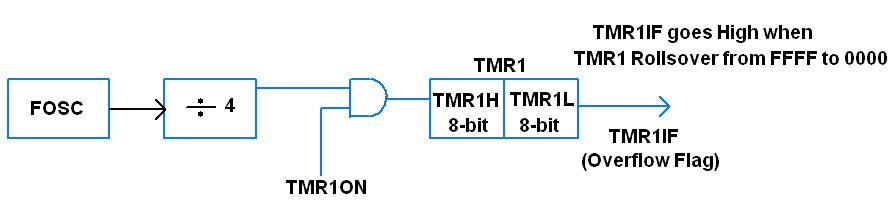
TMR1H and TMR1L registers can also be individually used to load the count in Timer1. These are both 8-bit registers.
To use Timer1 in PIC18F4550, Control and Status registers are used. Let us understand more about these registers of Timer1 in PIC18F4550.
T1CON: Timer1 Control Register
- It is used to configure Timer1 and also to start the Timer1.

RD16: 16-bit read/write mode enable bit
1 = Enable read/write of Timer1 in one 16-bit register which is TMR1.
0 = Enable read/write of Timer1 in two 8-bit registers which are TMR1H and TMR1L
T1RUN: Timer1 system clock status bit
1 = Device clock is derived from the Timer1 oscillator
0 = Device clock is derived from another source; it may be an internal oscillator or external crystal oscillator.
T1CKPS1 : T1CKPS0: Timer1 input clock pre-scale bits
These bits divide the clock by a value before it is applied to the Timer1 as a clock.
11 = 1 : 8 pre-scale value
10 = 1 : 4 pre-scale value
01 = 1 : 2 pre-scale value
00 = 1 : 1 pre-scale value
T1OSCEN: Timer1 oscillator enable bit
1 = Enable Timer1 oscillator.
0 = Disable Timer1 oscillator.
T1SYNC: Timer1 external clock input synchronization bit
When TMR1CS = 0
Timer1 uses an internal clock oscillator. So this bit is ignored.
When TMR1CS = 1
1 = Do not synchronize external clock input.
0 = Synchronize external clock input.
TMR1CS: Timer1 clock source select bit
1 = External clock from RC0 / T1OSO / T13CKl
0 = Internal clock (Fosc / 4)
This bit is generally used for counting events. To use Timer1 as counter, set TMR1CS = 1.
TMR1ON: Timer1 ON bit
1 = Start Timer1.
0 = Stop Timer1.
After Timer1 initializes, it continuously monitors the TMR1IF interrupt flag which gets set when the Timer1 overflows. TMR1IF is located in the PIR1 register as shown below.
PIR1: Peripheral Interrupt Register

TMR1IF: Timer1 Overflow Interrupt Flag
0 = Timer1 register overflow not occurred
1 = Timer1 register overflow occurred
TMR2IF: Timer2 Overflow Interrupt Flag
CCP1IF: Capture / Compare Interrupt Flag
SSPIF: Master Synchronous Serial Port Interrupt Flag
RCIF and TXIF: These are Serial Communication Interrupt Flag
ADIF: A / D Converter Interrupt Flag
SPPIF: Streaming Parallel Port Read/Write Interrupt Flag
Steps for Programming PIC18F4550 Timer
- Configure the T1CON register.
- Clear TMR1IF Timer1 interrupt flag.
- Load the count in TMR1 16-bit or TMR1H (higher byte) and TMR1L (lower byte).
- Set TMR1ON to start the Timer1 operation.
- Wait for TMR1IF = 1. Setting this bit to ‘1’ shows that Timer1 count overflows from 0xFFFF to 0x0000.
Example
Let us generate a delay of 1ms using Timer1.
/*
 Generating a delay of 1ms in PIC18F4550 using Timer1
 www.electronicwings.com
*/

#include "osc_config.h"		/* Configuration header file */
#include <pic18f4550.h>		/* Contains PIC18F4550 specifications */

#define Pulse LATB  		/* Define Pulse as LATB to output on PORTB */

void Timer1_delay();

void main()
{
    OSCCON=0x72;  		/* Configure oscillator frequency to 8MHz */
    TRISB=0;  			/* Set as output port */
    Pulse=0xff;  		/* Send high on PortB */

    while(1)
    {
        Pulse=~Pulse;  		/* Toggle PortB at 500 Hz */
        Timer1_delay();  	/* Call delay which provide desired delay */
    }
}

void Timer1_delay()
{
    /* Enable 16-bit TMR1 register, No pre-scale, internal clock,timer OFF */
    T1CON=0x80;

    TMR1=0xf830;		/* Load count for generating delay of 1ms */
    T1CONbits.TMR1ON=1;  	/* Turn ON Timer1 */
    while(PIR1bits.TMR1IF==0); 	/* Wait for Timer1 overflow interrupt flag */
    TMR1ON=0;  			/* Turn OFF timer */
    TMR1IF=0;  			/* Make Timer1 overflow flag to '0' */
}
Timer Using Interrupt
Generate Delay of 1 ms Using an Interrupt
Using Timer1 by calling an Interrupt Service Routine (ISR) eliminates the continuous polling of the TMR1IF flag. Also, the microcontroller can perform other tasks until an interrupt occurs. To use ISR for generating delay using Timer1, three bits need to be enabled – two in the INTCON register and one in the PIE register.
INTCON: Interrupt Control Register

The two bits – GIE and PEIE – in the INTCON register, as shown above, need to be enabled.
GIE: Global Interrupt Enable
Enable Global Interrupt for ISR to generate a delay.
PEIE: Peripheral Interrupt Enable
For some peripheral interrupts like TMR1IF, TMR2IF, and TXIF, we have to enable PEIE bit in addition to the GIE bit.
The third bit i.e. the TMR1IE in the PIE1 register can be used to enable the Timer1 Interrupt Flag (TMR1IF).
PIE1: Peripheral Interrupt Enable

TMR1IE: Timer1 Overflow Interrupt Enable Bit
1 = Enable the TMR1 overflow interrupt
0 = Disable the TMR1 overflow interrupt
Note: While generating a delay using ISR, the program takes more time to switch to ISR. Therefore, to avoid this we have to increase the count to compensate for the delayed time.
Steps for Programming PIC18F4550 Timer using Interrupt
- Enable GIE, PEIE, TMR1IE.
- Configure the T1CON register.
- Clear TMR1IF Timer1 interrupt flag.
- Load the count in TMR1 16-bit or TMR1H (higher byte) and TMR1L (lower byte).
- Set TMR1ON to start the Timer1 operation.
- When TMR1IF = 1, code will jump to ISR to execute it, and after execution control returns to the main program.
Program
/*
  Generating a delay of 1ms by using PIC18F4550 Timer1 Interrupt Service Routine
  www.electronicwings.com
 */

#include <pic18f4550.h>
#include "Configuration_Header_File.h"

void Timer1_start();

#define Pulse LATB

void main()
{
    OSCCON=0x72;	/* Configure oscillator frequency to 8MHz */
    TRISB = 0;  	/* Set as output Port */
    Pulse = 0xff;  	/* Send high on PortB */
    Timer1_start();

    while(1);

}
/***************Interrupt Service Routine for Timer1******************/
void interrupt Timer1_ISR()
{

    TMR1=0xF856;
    Pulse = ~Pulse;  	/* Toggle PortB at of 500 Hz */
    PIR1bits.TMR1IF=0;  /* Make Timer1 Overflow Flag to '0' */
}

void Timer1_start()
{
    GIE=1;		/* Enable Global Interrupt */
    PEIE=1;  		/* Enable Peripheral Interrupt */
    TMR1IE=1;		/* Enable Timer1 Overflow Interrupt */
    TMR1IF=0;

    /* Enable 16-bit TMR1 register,no pre-scale,internal clock, timer OFF */
    T1CON=0x80;

    TMR1=0xF856;	/* Load Count for generating delay of 1ms */
    TMR1ON=1;		/* Turn ON Timer1 */
}
Video
Components Used |
||
|---|---|---|
| PICKit 4 MPLAB PICKit 4 MPLAB |
X 1 | |
| PIC18f4550 PIC18f4550 |
X 1 | |