Introduction
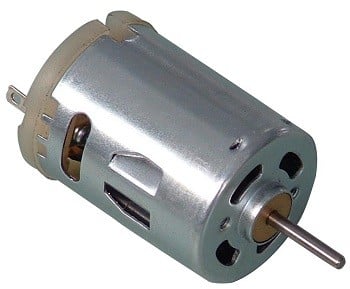
DC Motor
DC motor converts electrical energy in the form of Direct Current into mechanical energy in the form of rotational motion of the motor shaft.
The DC motor speed can be controlled by applying varying DC voltage; whereas the direction of rotation of motor can be changed by reversing the direction of current through it.
For applying varying voltage, we can make use of PWM technique.
For reversing the current, we can make use of H-Bridge circuit or motor driver ICs that employ the H-Bridge technique.
For more information about DC motors and how to use them, H-Bridge circuit configurations, and PWM technique, refer the topic DC Motors in the sensors and modules section.
Interfacing Diagram
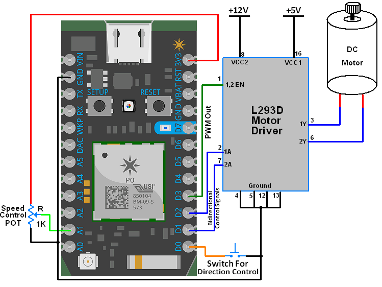
Interfacing DC Motor with Particle Photon
Example
Here, we are going to control the speed and rotational direction of DC motor using Particle Photon.
Here, potentiometer is used as a means for speed control and an input from tactile switch is used to change the direction of motor.
L293D motor driver IC is used for controlling the direction of motor.
PWM wave generated on the Particle Photon is used to provide variable voltage to the motor through L293D. In Particle Photon, analogWrite function is used to generate PWM wave.
Sketch for Direction and Speed Control of DC Motor
const int pot_input = A1;
bool d1 = HIGH;
bool d2 = LOW;

void setup() {
  pinMode(1, OUTPUT);  /* Motor control pin 1 */
  pinMode(2, OUTPUT);  /* Motor control pin 2 */
  pinMode(3, OUTPUT);  /* PWM pin for Speed Control */
  pinMode(0, INPUT_PULLUP);  /* Interrupt pin for direction control */
  attachInterrupt(2, motor, FALLING);  /* Interrupt on falling edge on pin 2 */
}

void loop() {
  int pwm_adc;
  pwm_adc = analogRead(A1); /* Input from Potentiometer for speed control */
  digitalWrite(1,d1);
  digitalWrite(2,d2);
  analogWrite(3, pwm_adc / 16);
}

void motor(){
  d1 = !d1;
  d2 = !d2;
  delay(200);
}
Functions Used
1. attachInterrupt(pin, ISR, mode)
- This function is used to configure the mode of interrupt event and declare the ISR for that interrupt.
- ISR in this function is the name of the ISR that will be used for this interrupt.
- mode defines when the interrupt will be triggered. There are four modes available to choose from:
CHANGE: trigger the interrupt whenever the pin changes value.RISING: trigger when the pin goes from low to high.FALLING: trigger when the pin goes from high to low.
Example, attachInterrupt(2, motor, FALLING) configures digital pin 2 as an interrupt pin with ISR named motor and which generates interrupt for every falling edge edge event on pin 2.
2. analogWrite(pin,value)
- This function is used for generating PWM on PWM digital pins
- value can be any number between 0 to 255. 0 being 0% duty cycle and 255 being 100% duty cycle.
Components Used |
||
|---|---|---|
| Particle Photon PHNTRAYH |
X 1 | |
| L293D Driver L293D Driver |
X 1 | |
Downloads |
||
|---|---|---|
|
|
dc_motor | Download |