GPIO of Photon
GPIO (General Purpose Input Output) pins can be used as input or output and allow particle photon to connect with general purpose I/O devices.
- In particle photon, there are total 18 GPIO lines available for the user.
- We can program these pins according to our needs to interact with external devices.
Basic GPIO Functions
pinMode(pin,mode)
- This function is used to configure the pin’s mode to behave as Input (INPUT), Input with pull up resistor (INPUT_PULLUP), or Output (OUTPUT).
digitalWrite(pin,value)
- This function is used to write a
HIGHor aLOWvalue to a digital pin.
digitalRead(digital_pin)
- This function is used to read the digital signal from the specified digital pin.
To know more about GPIO functions and their parameters you can refer Input/Output Functions.
E.g.
Let’s write a program to blink an On-board LED of Particle Photon when the switch is pressed.
Program
int button = D0;                      // switch is connected to D0
int LED = D7;                         // LED is connected to D7

void setup()
{
  pinMode(LED, OUTPUT);               // sets pin as output
  pinMode(button, INPUT_PULLDOWN);    // sets pin as input
}

void loop()
{
  // blink the LED when switch is pressed
  while(digitalRead(button) == HIGH) {
  digitalWrite(LED, HIGH);          // sets the LED on
  delay(200);                       // waits for 200mS
  digitalWrite(LED, LOW);           // sets the LED off
  delay(200);                       // waits for 200mS
  }
}
ADC of Photon
Particle photon has inbuilt 12-bit ADC with 8 channels (ADC0 to ADC7) i.e. it has eight ADC input pins as shown in the image below to read analog voltage from external device/sensor.
This means that it will map input voltages between 0 and 3.3 volts into integer values between 0 and 4095. This yields a resolution between readings of 0.8 mV per unit (i.e. 3.3 V / 4096).
ADC Channels/Pins
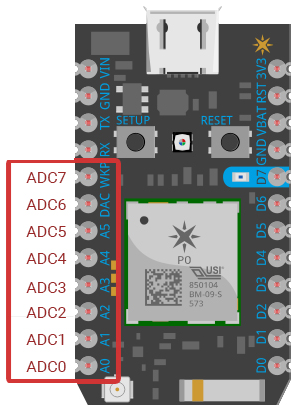
ADC Pins on photon board
The ADC channels on photon board are multiplexed with the SPI, DAC and WKP pins.
ADC Function
analogRead(pin)
- This function is used to read the analog signal from the specified Analog pin (pin).
To know more about ADC and their functions, you can refer Particle Photon ADC.
E.g.
- Let’s build an application which can be used to vary the brightness of LED connected to D3 using a Potentiometer.
- The potentiometer gives varying voltage which is applied to the ADC channel (here A0).
Program
Int LED = D3;              // LED connected to digital pin D3
Int analogPin = A0;       // potentiometer connected to analog pin A0
intval = 0;        // variable to store the read values

void setup()
{
	pinMode(LED, OUTPUT);      // sets the ledPin as output
}

void loop()
{
	val = analogRead(analogPin);  // read the analogPin values go from 0 to 4095
	analogWrite(LED, val/16);  // Generate PWM from values from 0 to 255
	delay(10);
}
DAC of Photon
- Digital to Analog Converter (DAC) is mostly used to generate analog signals (e.g. sine wave, triangular wave etc.) from digital values.
- In Particle Photon there are total 2 On-Board DAC Pins available, ADC6 (DAC1 or A6) and ADC3 (DAC2 or A3). We can set the output of DAC from 0 to 3.3Volt which corresponds to digital values from 0 – 4095.
DAC Function
analogWrite(DAC_pin, Value)
- This function is used to set the analog value between 0-3.3V which corresponds to digital values 0-4095.
To know more about DAC and their functions, you can refer Particle Photon DAC.
E.g.
Let’s generate a periodic analog signal which will in between 0-3.3 V on DAC pin.
Program
int value;
void setup() {
	pinMode(DAC1, OUTPUT);  //use DAC1 pin as a output pin
}

void loop(){
    value = 0;
    while ( value != 4095 )     //increament value till noe equal to 4095
     {
    	analogWrite(DAC1, value);
    	value++;                //increament value by one
     }

    while ( value != 0 )        //decreament value till noe equal to 0
     {
     	analogWrite(DAC1, value);
       value--;                //decreament value by one
     }
}
PWM of Photon
- Pulse Width Modulation (PWM) is a technique by which width of a pulse is varied while keeping the frequency of the wave constant.
- Particle Photon has On-board 9 pins or channels (i.e. D0, D1, D2, D3, A4, A5, WKP, RX and TX) for PWM generation.
PWM Function
analogWrite(pin, value)
- This function is used for generating PWM on PWM digital pins (pins D0, D1, D2, D3, A4, A5, WKP, RX and TX) for Particle Photon.
-
ValueIt is an integer value in the range of 0 to 255.
To know more about PWM and their functions, you can visit Particle Photon PWM.
E.g.
- Let’s build an application which will vary the LED brightness continuously using PWM on Particle Photon.
- LED should be connected to one of the PWM channels (here D1).
Program
intledPin = D1;        // LED connected to digital pin D1
int brightness = 0;     // how bright the LED is
intfadeAmount = 5;     // how many points to fade the LED by

void setup()
{
	pinMode(ledPin, OUTPUT);      // sets the pin as output
}

void loop()
{
	analogWrite(ledPin, brightness);

  // change the brightness for next time through the loop:
	brightness = brightness + fadeAmount;

  // reverse the direction of the fading at the ends of the fade:
	if (brightness <= 0 || brightness >= 255) {
		fadeAmount = -fadeAmount;
	}
  // wait for 30 milliseconds to see the dimming effect
	delay(30);
}
Components Used |
||
|---|---|---|
| Particle Photon PHNTRAYH |
X 1 | |