Introduction
- Particle photon is a complete IoT (Internet of Things) hardware development kit, it provides everything that we need to build a connected product.
- It has powerful 120Mhz ARM Cortex M3 microcontroller with a Broadcom Wi-Fi chip in a tiny thumbnail-sized module.
- Particle provides access to a free cloud service of the particle cloud. The Particle Cloud has some great features for building connected projects, including over-the-air firmware updates, an easy-to-use REST API, and firmware development supported by Web and local IDEs.
Features of Particle Photon:
- Processor: STM32F205 120Mhz ARM Cortex M3
- Memory: 1MB flash, 128KB RAM
- On-board RGB status LED.
- 18 Mixed-signal GPIO and advanced peripherals
- Open source design
- Real-time operating system (Free RTOS)
- Soft AP setup
- On-board Wi-Fi module
- Broadcom BCM43362 Wi-Fi chip
- 802.11b/g/n Wi-Fi
What’s on Photon Board?
Photon Board consists of a STM32 microcontroller, Wi-Fi, Switches, and LEDs.

Microcontroller and Wi-Fi:
- Photon board has ARM-based STM32F205 Cortex M3 processor with on-board Broadcom’s Wi-Fi.
RGB LED
- The RGB LED on Photon board is used to provide information about the mode the device is in. The color of the LED and its blinking pattern indicates which mode the device is in. To the various device modes of a Photon, refer Particle Photon modes.
D7 LED
- The D7 LED will turn on when the D7 pin is set to HIGH.
Setup and Reset Switch
- The SETUP button is on the left and the RESET button is on the right. You can use these buttons to help you set your device's mode.
Photon Board Detail

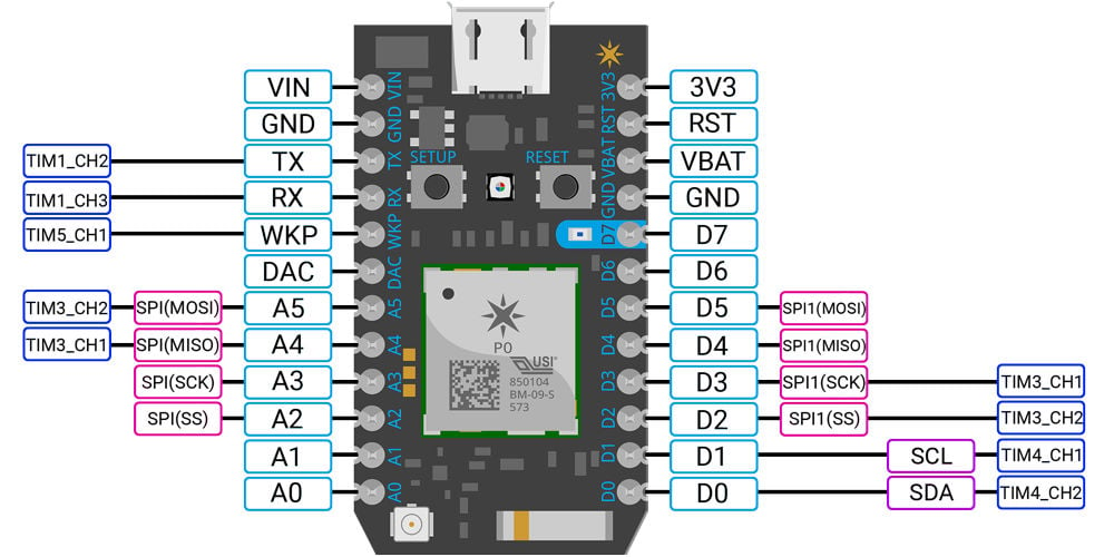
Pin Detail Diagram of Particle Photon
- 3V3: This pin is the output of the on-board regulator and is internally connected to the VDD of the Wi-Fi module. When powering the Photon via VIN or the USB port, this pin will output a voltage of 3.3VDC. This pin can also be used to power the Photon directly (max input 3.3VDC).
NOTE: When powering the Photon via this pin, do not put power on the VIN pin.
- GND
- WKP: This is an active-high input that allows you to wake-up the module from sleep/deep sleep modes. When not used as a WAKEUP, this pin can also be used as a digital GPIO, ADC input or PWM.
- VIN: This is the power supply pin to the Photon with a voltage range of 3.6 to 5.5VDC (internally regulated down to 3.3VDC). When the Photon is powered via its USB port, this pin will output a voltage of approximately 4.7VDC.
- Why 4.7 and not 5?
Well, the actual voltage will be the USB voltage, which is normally 5, minus the forward voltage drop (0.3V) of the protection diode.
- D0 - D7: These are digital only GPIO pins.
- A0 - A5: These can be used as digital GPIOs or as ADC inputs channels.
- DAC: This pin can be used as a digital GPIO, ADC input or as a DAC output.
- RX: Primarily used as UART RX, but can also be used as a digital GPIO, ADC input or PWM.
- TX: Primarily used as UART TX, but can also be used as a digital GPIO, ADC input or PWM.
- PWM: It has On-board 9 pins or channels (i.e. D0, D1, D2, D3, A4, A5, WKP, RX and TX) for PWM generation. The PWM pins are shown in above image named as TIMx_CHx i.e. TIM3_CH1, TIM3_CH2, etc.
- RST: This is an active-low reset pin for the Photon.
- VBAT: Supply to the internal RTC, backup registers and SRAM (1.8 to 3.3VDC).
- SPI: It has two On-board hardware SPI, namely SPI and SPI1.
The SPI pins on Particle Photon are as follows,
SPI SPI1
SS - A2 (default) SS - D5 (default)
SCK - A3 SCK - D4
MISO - A4 MISO - D3
MOSI - A5 MOSI - D2
- I2C: It has one I2C port. SDA and SCL pins are available on D0 and D1 pin respectively.
Components Used |
||
|---|---|---|
| Particle Photon PHNTRAYH |
X 1 | |